Clearing intersections
Use the Clear intersections tool when two surfaces intersect and you are not happy with the way both surfaces are offset. With the form, you can cut away a user-defined rim around the intersection and/or enlarge any existing gap between the surfaces. You can use this tool in combination with other tools in the Structure Builder, for example to retract or extend intersections.
For example, you can use Extend to other surfaces to extend the surface that you cut open, with a specified extension distance, to the intersecting surface.
Before (with 'Preview' switched on) and after cutting the purple horizon. click to enlarge
Before (with 'Preview' switched on) and after enlarging the gap. click to enlarge
- At the top of the form, select the folder that contains the tri-meshes for which you want to clear intersections. The Data, Imports, Seismic Interpretation and Surface Sets folder are available for selection.
-
On the Objects tab, select the type of intersection(s) for which you want to perform clearing:
Fault network Select this option to clear faults at fault-fault intersections. All fault tri-meshes in the selected folder are listed on the form and can be cleared.
Horizon - Faults Select this option to clear horizons at horizon-fault intersections. All horizon tri-meshes in the selected folder are listed on the form (faults are not listed as you can only clear the horizons, not the faults).
Horizon - Horizon Select this option to clear horizons at horizon-horizon intersections. All horizon tri-meshes in the selected folder are listed on the form.
Include intersections with unconformities Check this box if you (also) want to clear horizons at horizon-unconformity intersections.
-
From the list of the available horizons or faults, select the surface(s) that you want to clear by selecting the individual check box(es).
-
On the Modify Intersections tab, select one of the following options:
Cut Intersections Around the intersection, a rim with the size as specified under 'Gap size' below, will be cut in the horizon(s) or fault(s) that you selected under step 3.
Enlarge gap If a gap already exists between the selected surface (selected under step 3) and the intersecting surface, the gap will be enlarged up to the size you specify under 'Gap size' below.
Gap size Defines the cut-out distance around the selected tri-mesh intersections (see example below).
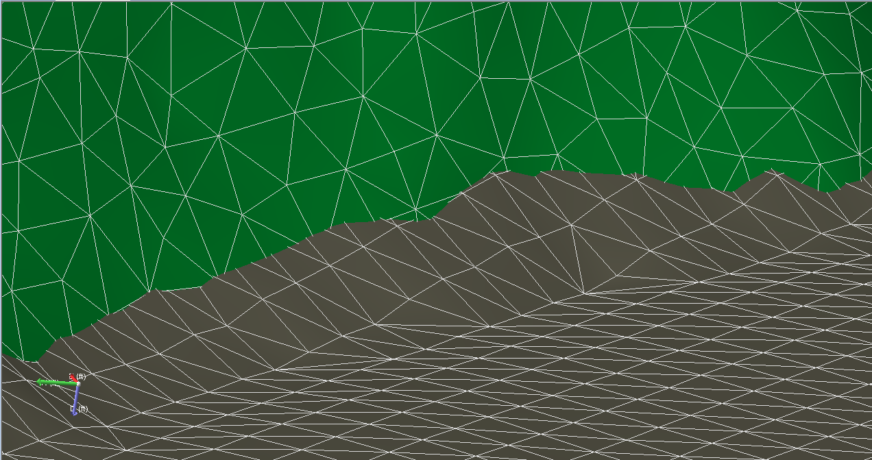
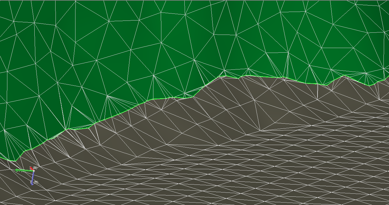
Original situation; a horizon (gray) intersects with a fault (green). click to enlarge
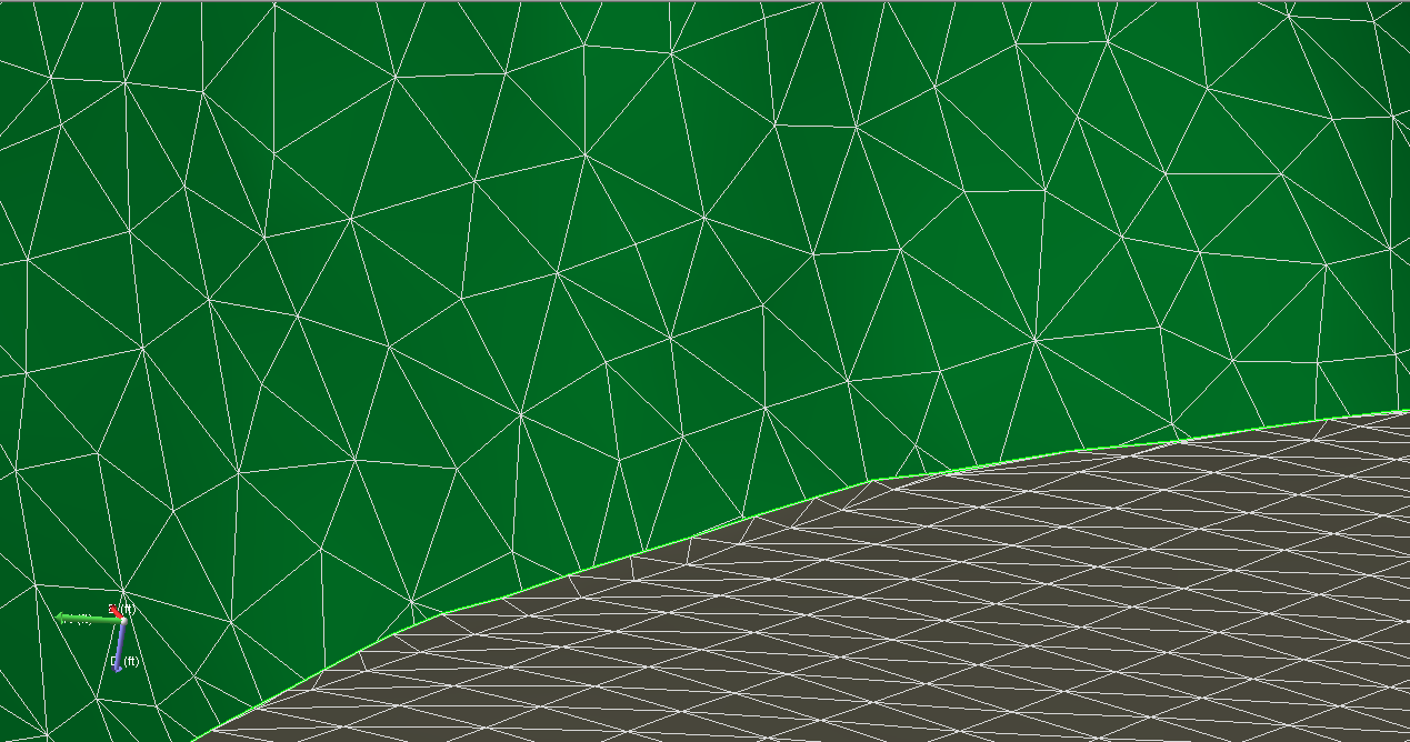
Cleared situation; the gray horizon has been cut at a user-specified distance around the fault, resulting in a fault gap. click to enlarge
-
You can select from the following options:
Keep watertight segments The algorithm does not create a gap at places where the surface intersection is watertight. The option is not available if you selected Include intersections with unconformities (see step 1).
Mutual cut This option mainly applies to the geomechanical workflow. With this option you introduce nodes on both surfaces at the same locations. Although no visible gap is created, both surfaces are cut at the intersection.
Original situation. click to enlarge
Cleared situation using mutual cut (compare with image above). click to enlarge
-
To identify intersections between tri-meshes, click Preview.
If the selected intersection type is Horizon – Horizon, the preview also shows unsolved Horizon – Fault intersections, if any.
-
On the Clear Intersections tab you can specify settings for the volume to be cut:
Blank in cylinder around intersection A volume with the shape of a cylinder is defined around the identified intersection. After the cut has been performed, no parts of the tri-mesh remain in this volume. Existing triangles are split up when they intersect the volume.
Blank in fault corridor The cutting volume is defined by a fault corridor which is defined by the combination of the specified gap size and those tri-mesh faults which are present in your fault model.
Smooth cut The triangles which lay partially inside the cutting volume are subdivided, or cut, and only the part inside the cutting volume is removed. This option leads to a smoother boundary but may cut the triangles into unfavorable shapes.
Remove triangles The triangles are not subdivided. Triangles which have at least one node inside the volume are removed from the tri-mesh. This option will remove triangles as a whole. That means that the triangle shapes will not be compromised, but it will lead to a potentially jagged boundary.
Dip Only triangles with a dip property larger than the specified dip value are removed inside the volume around the surface-surface intersection. This option only applies to the Remove triangles option.
Smoothness Only triangles with a smoothness property larger than the specified smoothness value are removed inside the volume gap size around the tri-mesh intersection. This option only applies to the Remove triangles option.
-
To apply the cutting algorithm to all intersection lines, uncheck Select individual intersection lines, and then click OK or Apply.
-
To apply the cutting algorithm to specific intersections only, check Select individual intersection lines, and then do the following to select the intersection lines: (The option is active once you have previewed the intersections.)
-
Select the Intersection lines option.
-
Use the arrows to move through the list.
-
This automatically selects the intersections in the list and sets the focus in the 3D view. Click the individual check boxes or right-click the list to make a selection from the context menu:
Select all Selects all intersections in the list.
Invert selection Inverts the selection so that the checked intersection lines are unchecked and the uncheck selected intersection lines become checked.
Select none Unchecks all the intersections in the list.
Make checked items visible Displays only the selected tri-mesh intersections in the 3D View.
Switch tri-meshes To cut the tri-meshes listed in the right column, select this option to transpose the columns on all rows that are checked. You can also switch the tri-meshes by double clicking the row.
Focus on selected item The 3D View automatically displays, and focuses on, the selected tri-mesh intersection.
Discard Temporarily exclude intersections from the process and move them to Discarded intersection lines list. You can achieve the same result by leaving intersection lines unchecked, but with the discard option you can keep track of the intersections more easily when you have many intersections. You can re-activate discarded intersections.
-
-
To clear the selected intersections, click OK or Apply.
To show the selected intersections in the 3D View, check Show selected items. - To activate discarded intersection lines, select the Discarded intersection lines option, select the intersection lines that you want to activate from the list, and then click Activate discarded intersection lines.